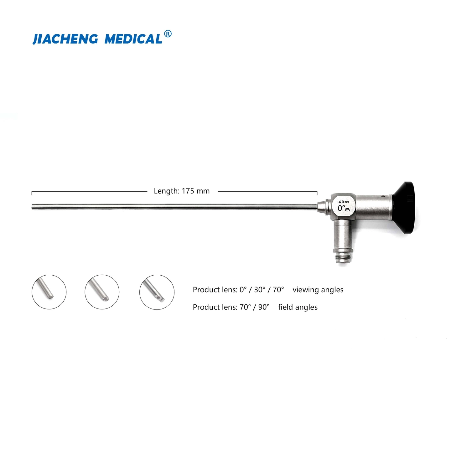


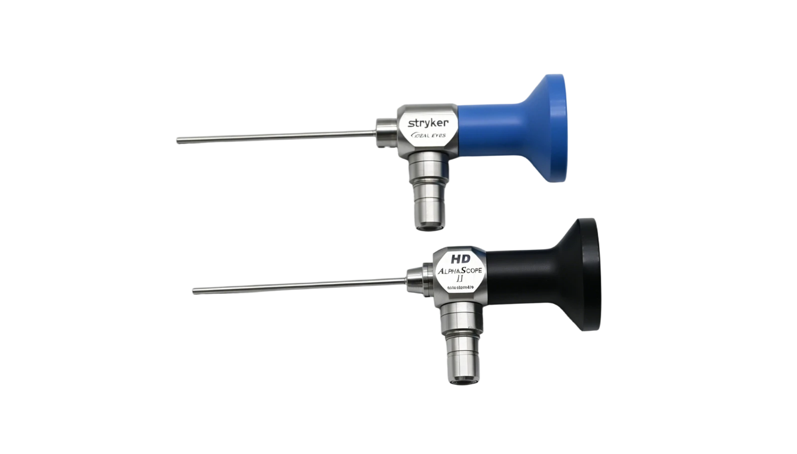
This technical case focuses on two jaw arthroscope models, the STRYKER 0502-119-010 and GIMMI E.8186.20. We break down the full workflow of optical lens disassembly, deep cleaning, assembly and optical calibration in detail. These two scopes share nearly identical internal optical architecture, so their troubleshooting logic and operational procedures are highly interchangeable. This guide serves as a universal reference for servicing similar arthroscopic optical systems.
Optical Path Disassembly
Start optical path teardown by extracting spacer tubes, diaphragms and adapter compression blocks. Use a hooked probe to reach inside the spacer tube, gently wiggle it loose, then lift it out with precision forceps. Lightly tap the scope housing to dislodge internal compression blocks. Careful control of applied force is required during this step to prevent the internal optical components from shifting or sustaining damage due to vibration. To ensure the alignment order of the optical components remains undisturbed during disassembly, a Reducing casing is used.
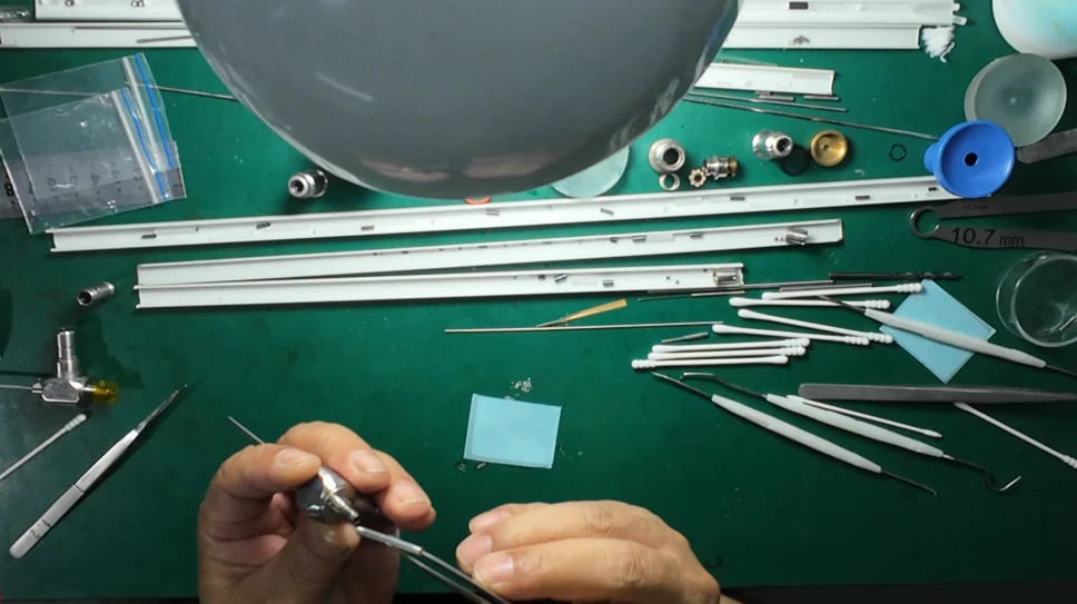
(Install Reducing casing)
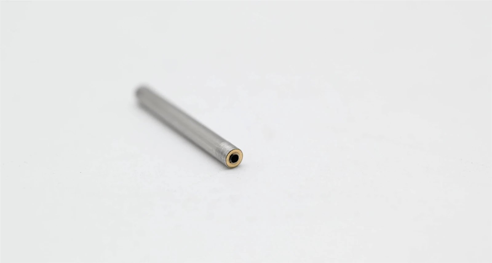
(Reducing casing)
The specific structure of the Reducing casing consists of a stainless steel tube with an outer diameter of 2.7 mm serving as the main body, with copper sleeves (2 mm thick) fitted at both ends; a stainless steel tube with an inner diameter of 1.1 mm and an outer diameter of 1.25 mm is installed inside. This tool requires high concentricity and functions to ensure that the rod lenses maintain their original sequence without alteration during disassembly and assembly.
Connect the reducing casing and extended external adapter to the arthroscope. Tap the scope body gently while conducting visual inspection until rod lenses are exposed from the scope tube opening. A method to confirm complete removal of all optical elements is as follows: Insert a thin stainless steel tube into the arthroscope, mark the position where the tube cannot advance further, then compare this marked depth with the total length of the scope outer tube to verify whether all internal components have been fully extracted.
Cleaning
After all optical elements are removed, move on to cleaning the interior of the scope body. First, scrape off adhesive residue at the distal tip with forceps, then polish residual glue layers using 1200-grit sandpaper to restore a clean metal surface.
To clean the inner wall of the scope shaft, push alcohol-soaked lint-free wipes back and forth through the lumen with a stainless steel tube.
The stainless steel tubing used in this case has an outer diameter of 1.0 mm and an inner diameter of 0.9 mm, matching the dimensions of the optical system. The cleaning process must be repeated several times to ensure no contaminants remain on the inner walls.
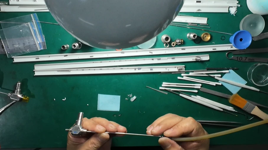
(negative-pressure vacuum purging)
After wiping, connect a suction device to the stainless steel tube to perform negative-pressure vacuum purging on the shaft inner wall, removing fine debris, lint and residual alcohol inside. Move the stainless steel tube forward and backward repeatedly during suction to ensure full cleaning of all lumen segments. Once cleaning is finished, seal both ends of the scope shaft with high-temperature sealant to block dust and avoid secondary contamination.
Test Assembly
The inner fitting sleeve is used to adjust the centering of the eyepiece fiber cable. If the sleeve is damaged or causes optical centering deviation, grind and repair it on a watchmaker lathe. When removing rod lenses, use eyepiece assemblies from STRYKER cystoscopes or hysteroscopes with matching inner and outer diameters as auxiliary tools to keep disassembled optical components in correct sequence.
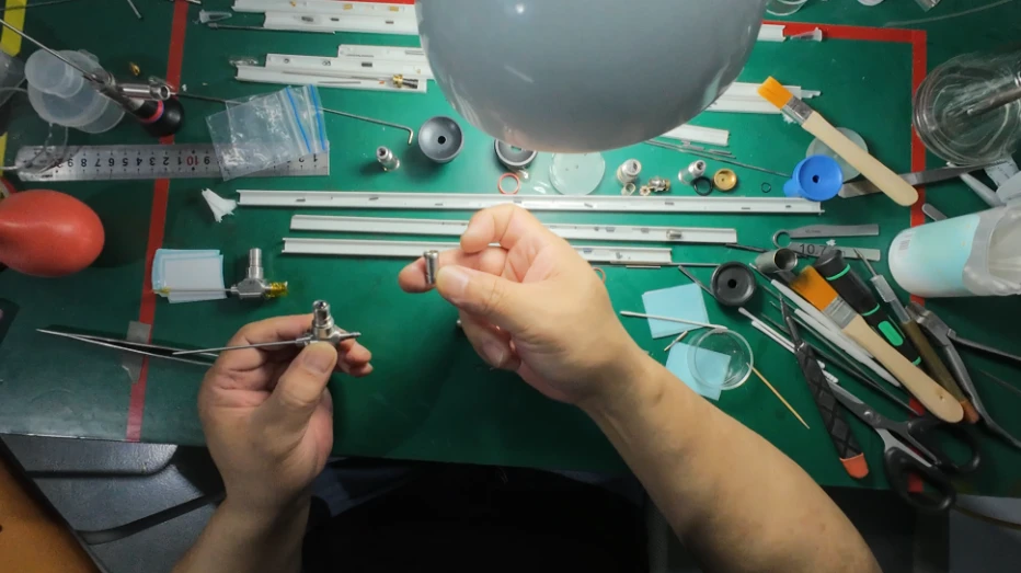
(Auxiliary disassembly tool)
Assembly demands extremely high operational precision. This repair case adopts a 40x head magnifier for operation; a high-power binocular microscope is also acceptable. Before assembly, both sides of magnifier/microscope lenses and all clamping forceps must be thoroughly cleaned to eliminate dust and oil stains.
About Tool Selection,,Extra-fine forceps are used for scrubbing and installing spacer tubes, while dedicated special forceps are required to hold optical lenses. This case uses lens forceps with a 1.1 mm round jaw opening. This design effectively prevents lens loss or scratching during wiping. The inner bore of spacer rings needs to be wiped with tiny lint-free swabs to guarantee cleanliness on all mating surfaces.
For this model of endoscope, it is best to completely disassemble, clean, and reassemble the entire objective lens assembly. The interior of the scope body is divided into three sections, making assembly from the rear toward the front quite challenging. During the procedure, first remove the rod lenses and spacers; then, heat the objective lens assembly to approximately 200°C and use a specialized tubular tool to push out each optical element one by one. Once cleaning is complete, insert the components sequentially starting from the distal end (the head of the scope) to reassemble the objective lens unit.
Objective Lens Bonding
The bonding process directly determines the tightness and service life of the objective lens group. This repair adopts custom high-temperature resistant sealant with the following properties:
It withstands temperatures up to 500°C, bonds well with glass and stainless steel, and exhibits excellent resistance to aging, acids, and alkalis. This semi-transparent adhesive features good flowability; when used to bond objective lens assemblies, it ensures effective penetration depth and airtightness-outperforming semi-solid adhesives in this regard. However, careful control of the working time is required, and heating to approximately 300°C is necessary if the adhesive layer needs to be disassembled. [learn more about...]
- Glue mixing:Blend an appropriate amount of glue evenly for about 2 minutes, then let it rest for more than ten minutes for pre-curing. Start application once the glue gains mild tackiness; its reduced fluidity prevents inward seepage. Adjust stirring speed according to ambient temperature: thinner glue under high temperature can be mixed slightly faster. Tiny microbubbles generated during stirring will dissipate naturally and do not affect final sealing results. Note that the glue shrinks slightly while resting. If incomplete filling occurs during encapsulation, surface glue will converge inward naturally via molecular tension to ensure full internal sealing.
- Glue Dispensing: Start dispensing once the glue reaches a thin stringing state. Clamp a 0.3 mm acupuncture needle as the glue applicator. Operation steps: First, stick the objective lens outward slightly with forceps carrying a small piece of 3M tape, re-clamp the lens with 1.2 mm micro-jaw forceps, pick up glue with the acupuncture needle and apply a uniform coating around the front half of the objective lens circumference. Reinstall the lens into the tube opening with assistance from a toothpick. After insertion, carefully check for glue overflow or accumulation around the lens perimeter.
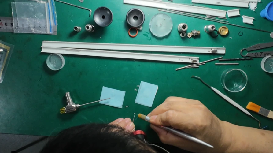
(Glue Dispensing)
- Excess Glue Removal: Let the bonded assembly stand for 8 hours; the glue gains partial hardness but is not fully cured at this stage. Scrape off excess glue with toothpicks or cotton swabs, heat cure the assembly to maximize bonding strength, then wipe clean with alcohol swabs. For lens surface scratches or stubborn residues that cannot be removed by simple swabs or alcohol, dilute polishing compound with clean water and buff gently with a toothpick tip wrapped in microfiber. Important reminder: Complete optical image adjustment while the glue is still partially cured, and confirm qualified imaging before final full curing. Fully cured glue creates permanent bonds that make subsequent disassembly and re-debugging difficult.
Eyepiece Calibration
To disassemble the eyepiece, cut open the outer eyepiece tube with a lathe turning tool. Subsequent re-soldering can precisely restore the original tube diameter and width without compromising assembly precision.
Before eyepiece installation, press spacer tubes fully into position with forceps, then mount the eyepiece adjustment base for fine-tuning fiber cable centering. Clean internal eyepiece threads thoroughly to avoid debris falling into the optical path during threading. Rotate the eyepiece inward slowly while observing the real-time optical image. If fiber cable misalignment , disassemble all parts, re-clean and repeat assembly.
(Clean internal eyepiece threads)
Final Repair & Assembly
Prior to full optical assembly, every single component inside the scope body must be cleaned separately, including both surfaces of each rod lens and the outer surface of every spacer tube. Hold optical lenses or assemblies with clean forceps, wipe lens surfaces in circular motions or outward spirals from center to edge using alcohol-dampened swabs to lift dirt rather than spread contaminants. Replace swabs frequently during wiping to avoid secondary scratches from dirty swabs. All assembly work must use pre-cleaned dedicated forceps and fixtures; direct bare-hand contact with lenses will introduce new contaminants.
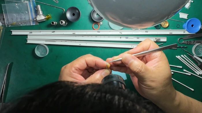
(assemble)
All custom tool selection, glue matching, bonding processes, disassembly and assembly sequences shown in this case are verified through repeated practical maintenance trials. We will continue sharing repair cases of other endoscope models in subsequent articles, stay tuned.